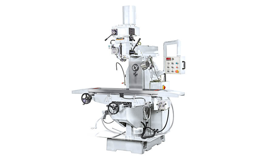
JY-28
(Auto)X1000 / Y400 / Z440
(Manual)X1000 / Y400 / Z440
- The main casting part is made of meehanite casting.
- The spindle run on high precision P4 class bearing.
- The spindle is one piece machined from SCM440 alloysteel, thermal refining, high-frequency and precision polishing.
- Milling head type:
-Steps (SHB) Inverter (CHB)
| 10 Steps |
| 60HZ |
75-125-195-280-420-650-1050-1610-2360-3500(RPM) |
| 50HZ |
60-100-160-230-350-530-860-1320-1940-2870 (RPM) |
-Inverter type used YASKAWA VFD.
- Used type B belt drive.
- Hardened and ground X,Y,Z axes slideway.
- Turcite-B coated on X Y ways.
- Square way design on Y and column slideway.
- X/Y axis double nut ball screw.
- Horizontal milling gear mechianism, maximum speed 1288/50HZ.
| 9 Steps |
| 60HZ |
92-204-241-251-536-590-660-1311-1614(RPM) |
| 50HZ |
73-163-193-201-428-471-527-1056-1288(RPM) |
- Horizontal bracket.
| Model |
Unit |
JY-28SHB |
JY-28CHB |
| Travel |
Longitudinal travel (M./A.) |
mm |
1000 |
| Cross travel (M./A.) |
mm |
400 |
| Vertical travel (M./A.) |
mm |
440 |
| Slideway X/Y/Z |
type |
△ / □ / □ |
| Quill travel |
mm |
140 |
| Overarm travel |
mm |
700 |
| Overarm swivel |
degree |
360 |
| Quill swivel (R&L)/ (F&B) |
degree |
±45/Fixed |
| Dist. from spindle nose to table |
mm |
100-540 |
| Spindle centerline to column |
mm |
180-880 |
| Table |
Dimension |
mm |
1370 x 300 |
| T-slots (Width x No. x Pitch) |
mm |
16 x 3 x 70 |
| Max. table load |
kg |
300 |
| |
Milling head |
type |
10 Steps |
Inverter |
| Spindle |
Speed |
60HZ |
rpm |
75-3500 |
55-3600 |
| 50HZ |
rpm |
60-2870 |
| |
Vertical feeds |
mm/rev |
0.04/0.08/0.15 |
| |
Main/Horizontal taper |
type |
NT40 |
| |
Quill Diameter |
mm |
110 |
| |
Horizontal spindle speed |
60HZ |
rpm |
92-1614 (9 steps) |
| |
50HZ |
73-1288 (9 steps) |
| Motor |
Main/Horizontal spindle |
HP |
5 |
| X-axis traverse |
HP |
1/2 |
| Z-axis elevation |
HP |
1/2 |
| Feedrate |
X-axis speed |
mm/min |
30-1300(9 setps) |
| Z-axis speed |
mm/min |
345 |
| Machine |
Space(L x W x H) |
mm |
2270 x 3100 x 2520 |
| Packing dimension(L x W x H) |
mm |
1800 x 2200 x 2100 |
| Net Weight |
kg |
2250 |
| Gross Weight |
kg |
2450 |
Standard Accessories:
- Draw bar
- Tool box and tools
- Tapping equipment of spindle
- Front finned bellows cover on Y axis
- Back chip cover on Y axis
- Working lamp
- Auto lubrication system
- X axis gear box
- Z Axis Rapid up/down
- Deluxe type operation panel
- Electric box
- Ball scerw (X/Y)
- Horizontal bracket x 2 set
- Horizontal arbor x 1 (25.4 or 27mm)
Optional Accessories:
- Power drawbar
- Power feed(Y)
- Servo feed(X/Y)
- Gear box(Y)
- Digital readout (DRO)
- Adjustable Automatic lubrication system
- Coolant system(Pump 1/8 HP)
- Chip tray


